SCD still now worky

Hi,

recently i got a sega cd and it no worky. I went through alot of the posts on the message board and managed to fix the problem; or so i thought.

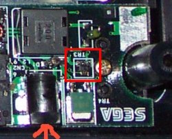
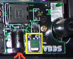
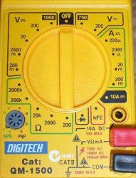
at first, i thought that it had to be the fuse for shure. So i replaced the fuse and alas, my multimeters read 13.9 volts across the fuse now!. I thought that the problem was solved so i put it all back together and went to fire it up. I didnt work the first couple of times so i jiggled it a little. Then i got it to fire up for a split second; both the green and red lights came on for a split second then nothing.

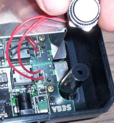
I then took the system apart again and checked the fuse and it was fine. I re-tested the soldering etc and then put the system back together again.

I had to jiggle it some more to eventually power on but it did the same thing; both green and red lights came on for a split second and the turned off.

Where do i go from here?

Keep in mind...

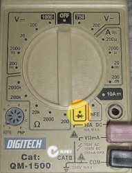
1. the fuse is replaced and when i probe the machine with the power in, i am reading 13.8V across the fuse so current is passing through.

2. I have checked both PSU's.

3. I have jiggled and then i have jiggled some more.

4. All connectors have been checked and cleaned.

Cheers
 
ok i re-checked my fuse and found that there is no voltage passing through.

the regulator is inputing and outputing 13.8v and the diode is also outputting 13.8v, what is next in line after these two?
 
hi,

i cannot seem to get a voltage reading from this device. It is labelled "TR3". it is boxed in in red.

So far the diode and voltage regulator work but something is still stuffed before the fuse.
 

Attachments

  • segacdrepair.jpg
    segacdrepair.jpg
    76.7 KB · Views: 181
  • segacdrepair.jpg
    segacdrepair.jpg
    76.7 KB · Views: 175
I'd really be suprised if there's anything before the fuse*, but can't you trace the path ot the voltage in to see what may or may not be working before the fuse?

Is this 'TR3' before or after the fuse?

*I don't own a Sega/Mega CD nor have I seen one in the flesh
 
If you can read a voltage drop across the fuse, then the fuse is blown. You should read near 0v across the fuse indicating that its a closed circuit.

When I said reading voltage on the fuse in my PM, I meant you need to put the ground on the voltimeter on the ground of the power input plug, and then put the VCC on the voltimeter on both sides of the fuse. You should read 13v on both sides of the fuse, relative to the ground on the power input. This means there is 0v drop actually across the fuse itself.

Sorry if you know this already, it might have just been the terminology in your post that threw me off.

If the fuse is blown (if it's a glass-tube type fuse, you can see that the thin wire inside is severed), then you might have the same problem I did. A 2.5A fuse is no longer strong enough. I had to move up to an 8A fuse. The 2.5A fuses just blew every time I turned the power on.

Also, this is probably obvious, but I'll just mention it anyway. Make sure the genesis is properly plugged into the side-connector when you're trying this. I don't think the segaCD will turn on unless the genesis also is connected and has power, but I could be wrong. If you have a genesis 2, the power connector often gets frumpy.

Also, try using the cleaning solution and brush (the same stuff you use to clean a genesis cartridge) on the input where the genesis side-attaches to the segaCD. I had one segaCD where the unit would not reliably turn on until I'd cleaned it.

Finally, make sure you didn't dislodge any of the white ribbon cables inside the unit. They pull out on both ends.

JMT.
 
After some more looking around i think that the problem may lie in the b963 power regulator. It is inputting and outputting 13.8V. But shouldnt it be inputting 9V and outputting 5V?

This site here... (curtis's??)

http://www.mrvfone.com.au/sega/7805.htm

says that every sega system uses this same power regulator; the LM7805. Although the one in the original sega cd is labeleed B963 L 2X. I am pretty shure though that they are the same thing as it is the only voltage regulator that i can see on the board. (boxed in in yellow)

I will try to re-solder this part with a new LM7805 but i want to make shure that it is right before i do anything. any ideas?

Here is a PDF about the LM7805 Family

http://www1.jaycar.com.au/products_uploaded/LM7512C.pdf

EDIT,

Hey JMT,

when i probe the fuse with the whole system turned on i read 0V on both sides of the fuse, ie, red on one leg and black on the other leg. Shouldn't i be able to read voltage across the fuse when it is turned on?
 

Attachments

  • segacdrepair2.jpg
    segacdrepair2.jpg
    20.8 KB · Views: 165
  • segacdrepair2.jpg
    segacdrepair2.jpg
    20.8 KB · Views: 122
Okay,

I tried some more testing,

Across the diode reads 13.9V

B963 is reading 13.8 in and 13.8 out

The fuse still isn't reading when i probe both ends of the fuse with the power on. The fuse though appears to be fine.

I tried putting one end of the multi meter directly on the solder points for the power input and then the other end of the multimeter on bothe the first and then second leg of the fuse but i still can't read anything. JMT can you show me on the picture what points i should be probing?
 
Originally posted by Berty@Sep 18, 2004 @ 01:34 PM

This site here... (curtis's??)

http://www.mrvfone.com.au/sega/7805.htm


Nope, not mine. Though I used it to fix my own MCD when it arrived DOA. It really does sound like you've got a dead fuse - all I can think is that the Pico type fuses are fragile as hell. You'd be better off replacing it with a full-sized fuse holder and a regular glass-type fuse (of an appropriate rating, of course).

The easy way to test is to use the continuity function of your multimeter. If you can show me a picture of your multimeter, I might be able to point out what this is.
 
Hi,

I did install a bigger fuse with a fuse holder, I have just been using the pictures that JMT sent me though as i have been too lazy to take my own shots. Here is a picture of my board with the fuse mod that i have done.
 

Attachments

  • segacdrepair_3.jpg
    segacdrepair_3.jpg
    41.7 KB · Views: 145
  • segacdrepair_3.jpg
    segacdrepair_3.jpg
    41.7 KB · Views: 212
Ok and here is a picture of my multimeter...
 

Attachments

  • multimeter.jpg
    multimeter.jpg
    34.2 KB · Views: 129
  • multimeter.jpg
    multimeter.jpg
    34.2 KB · Views: 127
This is a simple open/closed circuit test. Don't power up the MCD, just use the probes either side of the fuse. The display will change (or not) for a closed circuit. Test with just the probes touching each other to get an idea of what to expect.

That's the strangest looking fuse I've ever seen. :blink:
 

Attachments

  • post_2_1095571866.jpg
    post_2_1095571866.jpg
    24 KB · Views: 100
  • post_2_1095571866.jpg
    post_2_1095571866.jpg
    24 KB · Views: 122
when i touch each end of the fuse legs (on the board) the multimeter reads "001". That is the same reading that i get when the probs are just touching each other. So the fuse is okay then?
 
Yes I would take this to mean the fuse is fine. There is no way you could get that reading if the fuse was blown. Bad news for you I guess. :(
 
I can't believe the amount of magnets in this thing! Every single ribbon cable has a magnet running around it. Including the connection between the systems, which leeds me to the next point. I had the system completely stripped down and i took the shielding of the linking section (the part that joins the genesis up with the main cpu board of the sega cd unit). I found that the magnet that runs around that pcb was cracked but still in position. Im not shure how this would affect the mangetic field and even so, why is it needed? If anything, i would think that inducing a magnetic field would disrupt the flow of electrons.

Anyway, i have also noticed a second voltage regulator this one is an NEC 2405 9133E. I cannot seem to find any more info on this one from www.jaycar.com.au but that doesn't surprise me after seeing as they had no info on the B963 power regulator.

I can't take a reading of the 2405 though as it is hidden behind the ribbon cable when the system is turned on. When i run the same diode test on it though that i did on the fuse and the other power regulator, i am reading an input level of 1200 and an output level of around 900 alhtough i am not shure what this means.

Also, for anyone who wants hi resolution photo's of every componet top and bottom inside the sega cd just send me a message. I decided to take the shots while i had it totally dis-assembled.

If anyone knows where to find a schematic of the sega cd power board then i would be very greatful.

Cheers
 
Here is the NEC 2405 9133E Power regulator, any more infro regarding voltages would be gretaly apprciated.
 

Attachments

  • NEC2405.jpg
    NEC2405.jpg
    42.7 KB · Views: 168
  • NEC2405.jpg
    NEC2405.jpg
    42.7 KB · Views: 122
Originally posted by Berty@Sep 19, 2004 @ 01:34 AM

Hey JMT,

when i probe the fuse with the whole system turned on i read 0V on both sides of the fuse, ie, red on one leg and black on the other leg. Shouldn't i be able to read voltage across the fuse when it is turned on?

It sounds like you've got the ground on the wrong part of the power-input. Try putting one probe on all the different metal connectors coming out of the power input until you find the one that's the opposite of what's connected to the fuse. For me, I believe I was using the connector at the very top (relative to the pictures) of the power input cylinder doodle (most likely connects to the inside part of the plug).

If the magnet is cracked it shouldn't matter. It still produces the same magnetic field. It just helps guide the flow of electrons, and reduces interference.

JMT.
 
I've got an idea but i want to see what you all think before i do it. At the moment, the power problem lies before the fuse and after the voltage regulator. My idea is to solder a wire on the output leg of the voltage regulator to the fuse input.

JMT, you said that you were reading 13.8Volts after the fuse? Because even though i am bypassing something at least i will be getting the right voltage to the fuse, right?. I will use a 2 amp fuse in the fuse holder though before i do this. The way that i figure it is that worst i can do is blow the fuse?

Anyway, let me know what you guys think. I want to make shure that i am not missing anything.
 
OK, that didnt work but ihave traced the power problem further along the board. It seems that the fault now lies at the power inductor?? (Black box with "200" on the top.

I just have to wait for the shops to open now so i can get another.
 
Quick update, I just bought another model 1 and it works. YAY. but i haven't given up on the old one. I still need to go to the shops (on the other side of town) to pick up that inductor. I have been too busy playing sonic cd!
 
Back
Top