Hacked a 21pin mod to 20 pin saturn

Success!

It took me about an hour and a half to do this mod, but did the cuts and solders and it worked on the first try.

I didn't have any problems fitting the top on my saturn after doing this. My saturn looks exactly like pinchy's. In fact the numbers on the CD board are exactly the same.

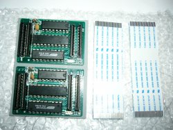
The problems I ran into were that the ribbon cable is now way too tight and is pulling on the mod board slightly. I'm planning on buying a longer cable to solve that. Another thing to be aware of is that the ribbon cable runs right underneath the spring opening mechanism of the drive tray. If the cable is stretched (not laying flat like it's supposed to), it could interefere with the closing of the tray.

Since the ribbon cable runs directly underneath the CD tray mechanism, it would not be possible to install the modchip on the CD board and still get the CD tray to close - at least not on my saturn.

Also, be careful when you're soldering from the far right pad (the one that's in the group of 3) - the one that wraps around to the front edge connector. It's easy to take the egde connector pad right off the PCB. That's what happened to me. Half of the trace came off and I really didn't get it very hot, so be careful.

Thanks to pinchy for researching this and to seal1 for the incredibly descriptive diagram. No more swap trick for me!
 
I am currently in the process of getting another model 1 saturn...i had the option of doing a 2 or 1 for a customer the other day he wanted the 1 done more, wish I had seen this thread sooner, I am gonng snag a chip from racket and do that, I am probably going to be publically doing saturn mod installs or premods if the need is around. depending on how much effort I have to put into the modded modchips (haha) will depend on the cost of modding the chips or doing an install with a modded modchip...I do PS2, GC, and XBOX installs on the regular so this is actually quite easier than what I am used to. For model 2's It'll probably be like $5 though, anyway will keep you all updated just toss me a PM if you need anything,

-OT-

Btw: Kick ass site I stumbled upon it on google somehow about an hour ago.
 
Originally posted by drk42@Sun, 2005-08-28 @ 02:28 PM

EMW10447-006E

Big V

ENR-007D

Here are some pictures:

http://www.54.org/condev/Saturn20to21pinMod/

BTW, on the modcard, that one red wire you see is insulated and is going through the hole where the solder was. I used #30 wire wrap for all wires.

[post=138876]Quoted post[/post]​


That saturn looks exactly like mine on the inside. Did you have any troubles with the ribbon cable being too tight? Mine fits, but I'm not comfortable with it long-term. Another thing I noticed is that your mod chip fit without having to bend or cut away the metal of the saturn casing around where the chip sits. I had to cut the metal with a dremel out on the side to get the chip to fit and not short out to the case.
 
Yo dudes, since it's a 3 day weekend...I figure I'll finally give this a shot (been meaning too for some time now).

Just a question though:

I've got a japanese model 1 with a component board attached to the top half of the case. For the power wire of the mod, do I solder to the red or orange wire of the PSU? (sorry, I've only ever done model 2 mods)

That's all and oh yeah, thanks for posting all the pics of this hack guys!

Let you know how it goes!

- See Ya!
 
(moved to other thread)
 

Attachments

  • p10504905lf.jpg
    p10504905lf.jpg
    782.3 KB · Views: 300
Originally posted by Zaksund@Fri, 2005-09-02 @ 08:30 AM

Yo dudes, since it's a 3 day weekend...I figure I'll finally give this a shot (been meaning too for some time now).

Just a question though:

I've got a japanese model 1 with a component board attached to the top half of the case. For the power wire of the mod, do I solder to the red or orange wire of the PSU? (sorry, I've only ever done model 2 mods)

That's all and oh yeah, thanks for posting all the pics of this hack guys!

Let you know how it goes!

- See Ya!

[post=139074]Quoted post[/post]​


You'll need a multimeter to double check your solder points for continuity and make sure your cuts don't have continiuty. So just use it to find the correct voltage.

To find the +5 wire, just set your multimeter on the right setting, then measure each post on the PSU and pick the one that's +5.
 
I'm waiting for my SSTKEY(?) chip from Japan that looks some what like those dual slot chip from UK...

Once I have I will do a bit of comparing to see whether they are in fact the same thing or different beast...
 
SUCCESS!! :D

Hey, thanks for the reply kahuna! I took it nice and slow with a magnifying lens & my multimeter, making sure everything matched up with the pictures posted. It took a little over an hour, and I was sweating bullets when I finally turned my Saturn on, but lo & behold this mod works!!

Not sure if you guys are still collecting cd board numbers, but mines:

ENR 007 B

Thanks for the help!!
 
What the heck!!?? :(

I got home Monday and tried out a burn...and it froze at the PAR loading screen.

So I thought, "Okay, that's cool...I'll just try a different one." which froze again.

"Oh crap no...", I started thinking.

The same freezing happened even when I tried originals (Shinobi Shin-Den, Golden Axe, Nights, FMM...)

So I take out the PAR and go to the CD player screen...and it turns out my Saturn is now calling everything an audio CD! Ugh!

So I pull out the mod and put the original ribbon cable in, but no luck...still the same thing. I probably woke up the whole neighborhood with my resounding "NOOOOO!"

Dude, what a cruel joke...why would it work for 2 days and then just stop??

Bah! I'm guessing where others have had continued success, that it's something I did wrong . I probably didn't warp the case enough before putting it on or bend the metal brackets enough.

Ah well, it's almost payday...I'll just replace them and try again in a bit.

Oh yeah, I used a regular modchip (had to cut the last trace off). But before I put may Sat in the storage closet, let me check my CD board number again to make sure it's right.

Here's to hoping tp221 has better luck with his mod.

dang...
 
Seems like you fried your modchip. It's happened to at least one other person in this thread too.

Was the mod board actually able to touch any metal? You should cut the extra metal out instead of bending it just in case. The ribbon cable can get pulled a bit if the drive tray mechanism hits it and the cable is so tight that it's possible that the mod board was pulled just enough to touch some metal.
 
WAHOO!

Today I joined the ranks of those who

have gotten this mod to work.

It was actually quite a pain in my a$$

I have the saturn version like pinchy's and my cable turned out to be long enough by twisting it so it fit around the side of the mod chip insted of over it.

Here are some tips that I picked up in my struggles:

1. use Seal1's drawing, it is 100% correct.

2. My Version of saturn has opposit pin markings on the mainboard Vs. the CD board.

let me explain, pin 1 on the Mainboard connected to what is marked as pin 20 on the CD board.

I had it backwards for the longest time, thinking pin1 should go to pin1. for your saturn just make sure you use whatever convention it was when you first opened it.

3. Plug the mod chip into the MAINBOARD, and not the CDBOARD!!! for some reason, in my head It seemed logical that it should work eitherway, and since it make the ribbon cable fit better, I wanted to put the modchip on the CDBOARD. The cuts and jumps we made make it so it doesnt work both ways.. I even dremeled out a nice spot for the mod chip to go next to the CDBOARD.

Thats it!, that should get you playing backups in no time.

Good Luck.

BTW, I'm willing to install or make the 21-20 pin mod, so send me an email.
 
Hello all, I've buyed this chip cause my chip for 20pin saturn is not working :( I'm searching all the picture posted on this thread. Does anyone have them? When I click it say that picture have been deleted, too bad.

Anyways thanks in advance :)
 
Originally posted by xor1337@Mon, 2005-10-17 @ 07:40 AM

WAHOO!

Today I joined the ranks of those who

have gotten this mod to work.

...

1. use Seal1's drawing, it is 100% correct.


welcome, good to hear from your success.

and thx.
 
Originally posted by theoutrider@Wed, 2005-06-29 @ 04:31 AM

I have a PAL Saturn here right now with a 21-pin ribbon cable and a 64-pin chip on the drive PCB - but even after reading this thread, I'm still not sure whether this will work on a 21/64-pin Saturn or only on the 20-pin ribbon cable versions.

If it also works on the 21/64 variant, is it still necessary on that to dremel off the leftmost (seen from the component side) pin on the chip?

[post=135977]Quoted post[/post]​


hello the link you gave for seal1s paintwork is not working, could you post the instructions please?

i have a grey jap saturn

thanks in advance.
 
Originally posted by NHJ@Mon, 2005-11-07 @ 01:01 PM

hello the link you gave for seal1s paintwork is not working, could you post the instructions please?

i have a grey jap saturn

thanks in advance.

[post=141450]Quoted post[/post]​


old pictures-links are broken and boardupload doesn´t work this days .... msg me w/ your email-addy
 
Back
Top